Thursday, 31 December 2009

ECU diagnosis


An increasing number of jobs refered to us are for ECU diagnosis.

This is often due to the expense of the new unit, or to confirm the diagnosis of another garage.

We can't test ECU's on site, but there are a number of tests that can be carried out, these tests simply prove what its not, until you are left with what it is. In many cases the ECU.

Due to the coding and immobiliser functions within modern ECU's it is sometimes better to repair the old unit.
A few simple procedures such as a global scan, for codes in all modules, not just the suspect ECU or modules as they are now known.
Check power supplies, grounds and primary signals if these are satisfactory then it's a good chance the ECU is at fault.
Many of the vehicles we test for module failure have wiring and connector faults, not ECU failure.

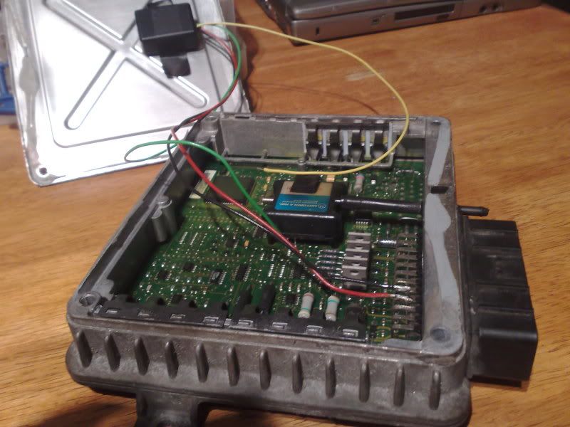
In this case a Landrover was refered to us for a second opinion, the owner did not trust the diagnosis or the the repair estimate.
A quick scan of the modules (results shown above) produced a number of codes.
Checking grounds, connections and lives proved satisfactory, all the primary signals to the ECU were present however there was no injector output.

As it was the holiday season, the ECU repair facility sent a un-locked ECU for the owner to use over the holidays. The repair will prove less costly than the new ECU the owner was quoted by the previous garage, plus having seen for himself that a replacement unit has fixed the intermittent non start he was more than willing to trust our diagnosis.

Sunday, 27 December 2009

Not so Noble


Had a call to look at a Noble M12 GTO 3 R, not sure what this is.....nor was I.
A bit of reseach and I was in the picture, a British performance car built in small numbers.

Powered by a ford v6 as found in the mondeo but with 2 small differences twin turbo's.
The car in question had a running problem.
It was impossible to test drive the vehicle effectively due to the weather conditions, but it appears to be over boosting.

A new turbo has been fitted, this is the most likely cause, incorrect waste gate pre-load.
We suggested the shop check both turbo's and adjust accordingly.
They reported back informing us they had found a seized wastegate, however the car is booked on the rollers to confirm diagnosis.
More to follow......

Sunday, 13 December 2009

Non Start after repairs


We are often called upon to advise other garages when they can't fix vehicles.
This reinforces the training need.
It is often impossible to diagnose vehicles over the phone but we can suggest procedures to garages.
This was a classic example;
The vehicle in question had been repaired in another shop.
After remedial work the car refused to start.
The only fault code 52 related to the ECU permanent memory.
The shop had sent ECU's away to remove immobiliser function, replaced transponders and receivers for the keys. But now was at a dead end.
We suggested checking fuses, however after a short time we were informed all the fuses were found to be ok.
So we suggested checking EARTH paths for the engine ECU.
The next call thanked us for our help, and enquired about courses in the near future.

Wednesday, 9 December 2009

Common Rail


Diesel common rail has been around for a while now and we are starting to see more and more problems with these systems.
This being the case we use a number of different techniques to diagnose problems.
The pump is the heart of the system, one quick test we perform is cranking pressure generation.
These pumps have to deliver around 250 bar during cranking or the engine will not start.
So this test can be carried out using a scan tool, or scope.
I prefer the scope as I like to measure the time taken to develop this pressure.
The different systems have similar rise times and it can be a good indication of system functionality.

This example from a cp1 Bosch system fitted to a Peugeot Hdi shows a pressure rise of less than 1 sec. You can see the pump strokes contribute evenly this is a good pump, with good primary supply and no excessive leakage from the high pressure components.

Wednesday, 25 November 2009

Serial Data analysis for DUMMIES.


The ability to graph serial data makes analysis easy.

In this example the CTS output is being monitored to check for the cause of a 17704 fault code.

The code relates to a cooling system malfunction, and the ECU monitors the CTS for this code so its a good place to start.

We were expecting an error in temperature reporting or thermostat failure.

We were not disappointed.

Monday, 23 November 2009

Fuel Trim in action

There are plenty of articles and much is spoken of Fuel Trim analysis.

However the message has got confused, after attending seminars by 'experts' I was alarmed at the level of miss information.

Looking at oxygen sensor readings will show trends, however the Trim will continue to adjust fuelling so fuel problems are effectively masked, ensuring correct catalyst operation. So much so that the O2 sensor could show normal response, despite abnormal conditions.

One 'expert' suggested measuring response time of the pre cat sensor after over run as a method of measuring short term fuel trim, utter nonsense. The response time will depend on many variables, the biggest being the distance from the exhaust valve that the sensor is positioned. The quanity and temperature of the exhaust gas content will also effect the response time. How can a 1.1 N/A expect to have the same response time as a 2.0 turbo.

Another misleading piece of advice was the true condition is always reported by the post cat sensor. While this has some foundation, the post cat sensor will report on the effectiveness of the catalyst, so should show less oxygen than the pre cat in a correctly fuelled engine. If the catalyst is faulty the post sensor may indicate a lean condition, that simply does not exist.

The best way to evaluate the trim is to use serial data, comparing long and short term trim at different engine load and speed sites.
Forcing the engine lean (on overrun) and rich (on snap throttle) will show oxygen sensor response but little about trims.

Friday, 6 November 2009

Burnt Out


I was called in to look at a Ginneta G50 race car that was burning out relays.

Used in the British GT Championship it would start and run fine but would burn out its relay before the end of the race resulting in a DNF.

A new pump and a few different relays had been tried, but the fault remained.

I used a amps clamp to test current draw, on the control and output sides of the relay.

I discovered that the control side of the relay had abnormal current draw, but where was the resistance, classic cause and effect diagnosis.

The effect = burnt out relay.

The cause = excessive resistance in the circuit.

A quick check with the scope(image shown above) showed higher than acceptable volt drop on the earth circuit.
This after prolonged used caused the relay failure, replacing a section of loom had this GT4 back on the grid.

Thursday, 29 October 2009

Fuelling around


This Rover 75 had defeated the garage that had carried out a headgasket job but would not start afterwards.
This is a common failure and is due to the fuel tank design, and how fuel is pumped from one side of the tank to the other. The accumulator often comes apart. This results in no fuel to the engine.
All that is needed is to screw the two parts back together and prevent them coming apart again with a self tapping screw.
Once this was carried out the engine spluttered into life and revved up and down on its own.
A sure sign of an air leak.
Finding leaks is often a task undertaken with a smoke generator. But this one was so bad it could be found with your hand, a hole in the plastic manifold.

Thursday, 22 October 2009

Oscilloscope Testing

This can appear to be somewhat of a black art.
However with a little practice, it becomes second nature. If you can use a multi-meter you can use a 'scope'.
An oscilloscope displays a picture of Voltage over time.
The waveform or pattern produced can tell far more about the circuit being tested than a changing display on a multi-meter.

Thursday, 15 October 2009

keeping in Trim

Decoding fuel trims can be a key part of engine diagnosis.
But what is a fuel trim?
The fuel trim is the ECU's adjustment of the fuelling based upon information received from the oxygen sensors.
A positive trim is the ECU adding fuel to the normal amount injected for the conditions reported by various sensors.
A negative trim is the ECU removing fuel.
They can be a used to diagnose various running problems, from air leaks to fuel pumps.

One such problem had baffled a number of garages, a Fiesta with a running fault.
On the road performance was much reduced, and it posted an air mass meter fault code.
The component had been replaced (twice), and wiring checks proved that no wiring faults existed. Live data showed only 2 volts from the AMM during acceleration tests.
However fuel trims showed -18% at tickover.

So despite low outputs from the AMM the ECU was removing fuel, this seemed to stump the previous garages. New O2 sensors were fitted before the ECU was sent away for testing.
The ECU returned with a clean bill of health.

So the question remains what fault would result in low AMM voltages and minus fuel trims?
Restricted engine breathing, so the usual suspects were checked. Air filter, intake trunking, and exhaust inc CAT condition.
A blocked CAT was found to be the cause.

Monday, 5 October 2009

Rolling road tuning

Having access to a chassis dyno is vital, if you want to know if you are improving the performance of your engine.
A 205 gti road rally car recently came to us for some checks following a head gasget replacement. A skim of the head was required and the owner wanted to make sure this had not upset the previous settings.
A base run to check fuel ratios, detonation, and power output showed a healthy spred of power but with some detonation. Slightly rich mixtures across the rev range and no thermostat resulting in low operating temps.
Adjusting the fuel pressure reg showed increased torque readings with slightly less fuel pressure. However these 'gains' were reduced by retarding the ignition timing to prevent detonation.
Repeating power runs with a set operating temp closer to 86 degrees C than the previous 58 degrees C showed a slight loss due to heat soak.
Advancing the cam timing showed a little improvement but not enough to keep testing.
Rolling road time is expensive and knowing when to stop is important, otherwise repeated tests cost more than they bring in improvements. But if you want to wring the last few bhp or lb/ft out of your engine you have to test all the possible settings to see if they can make the difference.
The importance of repeatable results is paramount, otherwise you are wasting your time.
We use a dyno that gives often depressingly accurate results time after time, with the ability to overlay previous runs to where or if you have made that improvement.

Tuesday, 22 September 2009

Lack of puff

Having repaired the 620 ti the performance wasn't what you would expect from a 200 bhp saloon. It was somewhat flat, and lacking the urgency that you get with high performance turbo charged motors.
To investigate I fitted a boost gauge, upon opening the throttle boost built up slowly to a max. of 7psi. At first this would point to the electronic boost controller. A device that 'bleeds' boost away from the actuator increasing boost levels above the spring pressure of 7psi.
However this vehicle is fitted with a manual boost controller, so it isn't a problem with the electronic control. Increasing the pressure setting of the MBC didn't increase boost levels.
This points to a problem with the actuator, often with older cars the spring tension weakens, and more pre-load is required to restore correct operation. However too much pre-load results in potentially damaging boost spikes and boost creep at higher rpms.
The correct pre-load can be tested with a simple pump and gauge, increase pre-load to the desired pressure. This is done by adjusting the length of the actuator rod.
After adjustment test drive the vehicle checking boost levels under differing driving loads and speeds.
I had to reduce the settings on the MBC resulting in 12psi of boost (max safe level with std engine) for much of the WOT speed range.

Saturday, 19 September 2009

Fault Codes what do they mean?

When you read the codes stored in an ECU you are hoping to find a "silver bullet".
These "bullets" tell you which part to replace or repair, however very few ECU's seem to be loaded with these. Instead the code is an indication of the problem area.
The actual fault still needs to be determined using diagnostic procedures.
Using EOBD the problem area is identified by the code, it then further divides the system into sub systems and finally components/specific operations.

P0420 for example;

P= Powertrain
0= Generic Code
4 = Emissions
20 = Catalyst efficiency below threshold

The prefix letter denotes the system
p = powertrain
B = body
C = Chassis
U = Network

The first number denotes the type of code
0 = Generic (all cars report the same code for a similar fault)
1 = Manufacturer specific ( this can differ from one model to another )

The second number identifies the subsystem
In powertrain;
1 = Fuel or Air
2 = Fuel or Air
3 = Missfire
4 = Emissions
5 = Vehicle or engine speed
6 = Control systems (ECU or output circuit)
7 = Transmission
8 = Transmission
9 = SAE reserved
0 = Fuel pressure control

The final two number numbers identify the setting variable.

Armed with this information it can sometimes help if you get "Blanks" these sound like a real bullets but are a long way short of being a silver bullet.
"unidentified fault codes"

Friday, 28 August 2009

Testing Earth Circuits


The way in which earth circuits are tested is a critical step in your diagnostic routine.
Becoming familiar with effective ways to test Earth's will save trouble and miss diagnosis.
Recently I was asked to look into a V.A.G. vehicle with a fault code that would not clear, despite the changing of many of the components, including relays, sensors and the ECU.
A test of the earth circuit proved a high resistance at the Earth point on the bulkhead.
A simple clean up of the connector and the application of some battery post grease restored normal operation.
But how do you test earths effectively?
The answer is Volt drop, measure the earth circuit just like you would test the voltage in a battery.
However the circuit must be use and the results should be no more than 0.2V or 0.5V cranking.

Sunday, 23 August 2009

Turbo Trouble


Had to fix this one, I bought a vehicle as it had a running problem that couldn't be fixed.

Or so it appeared, it was owned by a mechanic and despite spending a considerable sum of money on the car over the last few months he had given up.

The car in question was a Rover 620 ti, this uses the MEMS engine management system.

It is important to note what system is fitted before diagnosis can take place, different systems handle errors in different ways.

The problem was a starting fault that got worse when the engine was hot.

First things first with any diagnosis, the basics, this includes 10mins of look and feel, making sure the car has fuel in it.

To that end 30 litres of fuel were purchased.

A quick code read showed multiple codes, no doubt due to removing sensors connections and testing by the previous owner. As a starting fault it is possible to clear codes, to eliminate any historic codes and only current codes relevant to the fault will remain.

As the car will not start at all when hot, this will prove beneficial, reducing the number of tests required to prove the diagnosis.

The fault code remaining was Map sensor.

This didn't concern too much, but a look at live data showed a reading of 800-830KPa at idle once it had cooled down and eventually started. The expected value would be 300-350.

Such poor engine vacuum would give the sort of fault I was faced with, but the car drove too well to have a engine problem. plus this MEMS system will use the TPS (throttle position sensor) value as a substitute for MAP values giving engine load information to the ECU.

I tested for coil and injector outputs from the ECU during cranking. All Ok.

But his doesn't prove fuel delivery, so a quick fuel pump test as used on the formula Renault's proved the pumps ability to deliver fuel, and a pressure test showed normal results.

As this left no other explanation for the non/poor start it must be the erroneous MAP reading that is the cause, as the MAP sensor is inside the ECU it normally requires a replacement ECU.

However in the paperwork with the car I noticed a receipt for a Collins power chip.

This 'chip' is a frequency limiter that prevents fuel cut off above a given boost pressure allowing more than standard boost pressure.

It was found that to fit this 'chip' requires soldering a by pass wire in the MAP sensor circuit.

This soldered joint had failed, a quick visit with the soldering iron restored normal starting and improved performance from the increased levels of boost.


Word of caution do not increase boost levels above 12psi on this engine without internal modifications as piston failure will result.

Tuesday, 11 August 2009

Smokin' Fuel Pump relay


Formula Renault single seater, running mappable
ECU was getting hot under the collar.
To carry on racing the relay had been by-passed.
However this isn't safe practice and the cause had to be found.
The rating of the relay was checked to ensure it was up to the job. Then the current draw of another car was measured. (left).
A peak of 12 amps and a running current of aroun 10 amps.

With this in mind I was expecting to find a fault either in the wiring or the pump resulting in a much higher current draw. This was measured at the pump wiring with the by pass fitted. This would exclude the ECU and associated wiring. the result is shown. (right).
A peak of 14 amps and a running current of 12 amps, however it is running much slower than the previously tested pump.
When tested at the relay (with the by-pass wiring removed) no current draw was observed.
The car would not start, and the fuel pump refused to prime.
Closer inspection found a broken terminal going into the relay block. Not on the relay that was getting hot but on another that shared '+' feeds.
Once repaired and re tested none of the relays were smoking and the car barked into life.
I quick check of the 'fuel pump relay' showed little more than 0.2 A draw, it wasn't the fuel pump relay, but the ECU supply. The broken wiring resulted in back feeding and this in turn over heated the relay circuit. Re routing and not securing the relay block to the chassis should prevent it happening again.


Monday, 10 August 2009

Door won't open!!


Just had to let you guys know about this one.

A workshop had spent hours trying to open the door on a Peugeot 1007.

Convinced they had a door lock fault they had almost destroyed the trim on the door trying to remove it, while the door remained firmly locked.

A global scan, that is a scan of all the electronic control units fitted to the vehicle revealed a fault code relating to the fuel filler cap. A new filler cap sensor and loom was fitted and hey presto the door opened.

But why, these vehicles are fitted with a sliding door that is prevented from opening when the filler cap is opened. This is a safety issue as the door would hit the fuel nozzle if it could be opened during re fuelling. With the sensor faulty the safe mode is locked.

Saturday, 18 July 2009

P0420 AGAIN!

This fault code seems to be cropping up more and more, by that I mean it comes back after the fix. But why?
Firstly lets understand the fault code and how its generated.
Modern cars have 2 O2 sensors, the first before the cat, monitors the oxygen content of the exhaust gas. It uses this to adapt the fuelling via the fuel trim to keep the mixture within acceptable limits. The 2nd sensor after the cat monitors the efficiency of the cat. If the switching ratio of the O2 sensor is similar then the cat isn't working. This ratio is monitored and once a set ratio is exceeded the fault code P0420 is set.
So why does this fault code come back?
There are 2 causes poor quality replacement parts, and not fixing underlying causes.
If you are presented with this code ensure before fitting a new cat the reason for the failure is correctly identified and fixed. Missfires will make short work of a new cat.
Once the cause is rectified ensure the replacement is of OEM quality, too often the returning code is down to the quality of the replacement parts.

Friday, 17 July 2009

Rally car trouble

This week we have a rally car to deal with. Once warm it cuts out, will not re-start until cold again. A simple temperature related problem so why has it proved so difficult to fix?
time to investigate.

Turns out a relay is failing.

Tuesday, 14 April 2009

No Codes No Fix

A local garage a had a few problems with this one.
The car cut out, and will not restart.
If left for 5 mins or 5 hours it will restart but cuts out then won't start again.

They tried to scan it for codes, but this resulted in the dreaded no codes found.
The vehicle did not support EOBD so no pending codes or freeze frame data.
This is where you need to have a basic understanding of the control systems.A few quick checks, and hey presto the Crank Angle Sensor is found to be faulty.
Once again checking inputs and outputs with a scope provides the answers when scan tools fail.
A new sensor restored normal operation.

Saturday, 4 April 2009

No fault codes what next?


Technicians are becoming more and more dependant upon fault codes. This is due to the increasing complexity of modern vehicles.


But how do you tackle diagnostic problems without codes.


The first example this week was a non starting Clio 1.4 single point injection.


No communication with the scan tool thus no codes.


Where do you start with this kind of problem?


One of my first tests is power to the injectors, this is a good idication of ECU, main engine relay, & earth are all ok.
In this case we had no power at the injector. The reason is proberly the cause of the non start.
Using the Autodata wiring diagram shown it is possible to work out where the feed comes from. The fuel pump relay, this checked out OK, so the main engine relay was tested, I tend to bridge them as a quick test and after this not only did the engine start but communication with the scanner was restored. Problem solved or was it, I haven't proved how it had failed. It turns out the switched earth signal from the ECU has gone missing, the wiring had gone Open Circuit.
A quick repair restored normal operation, but why had a new ignition coil been fitted in an attempt to get this vehicle going?
The garage had tested for a spark during cranking, not being able to gather codes resulted in a guess. The guess was based on previous experience of this system where coils had been known to fail.
Following a TESTING procedure that I have refined over years of diagnostic testing prevents costly mistakes.