Vehicle diagnosis is like an onion it can have many layers and make your eyes water.
I was called to a garage to check out a Toyota Rav 4 they had in for diagnosis. The vehicle was very flat hardly able to pull away under its own steam. The fault history had been cleared and the only fault remaining was O2 sensor bank 2 sensor 1. Unsure which sensor is bank 2 sensor 1 they were going to order a pair. The price soon put a stop to that plan. This vehicle is fitted with wideband sensors which are much more expensive than the narrow band type. I did a quick inspection of the wiring, and quickly tested the heater circuits using a scope. Bank 2 sensor 1 had a open circuit heater. A new sensor was ordered, how ever this was unlikely to cure the flat running problem.
I had a quick look at the live data, and noticed the air mass was under reading at WOT. I checked this with a scope and sure enough it was only hitting 2.7V on snap acceleration. It should be closer to 4.5V. I checked the supply and earth connections both were fine. So a new air mass meter was added to the order.
After both components had been fitted and the codes cleared the vehicle displayed normal driving characteristics. As is often the case the fault code and mil light did not relate to the symptoms. The customer wanted the light switched off, so I guess that renewing the O2 sensor would of fixed that, but the air mass was causing the flat running. This is typical of engine management faults when you will be presented with multiple codes, or multiple faults or even both. You have to peel these layers back to reveal the fault(s). The cost of the parts can make your eyes water.
Thursday, 13 January 2011
Tuesday, 30 November 2010
The heat is on........
Had a call to look at a 2.0 Renault Clio 182, it had been around a few garages and the owner was fed up with O2 sensor diagnosis. The first garage fitted an universal sensor after reading the fault codes. The second garage fitted two Renault sensors as he only fits genuine parts. The third informed the owner that he suspected the oxygen sensors!
At this point he asked for a second opinion. This is where I enter the equation. The garage had asked me if I had seen this sort of fault before. Many times I explained, so they wanted to know the cause. Many things I explained. So armed with a list of possible causes and a warning to make sure the cause was found and not the effects.
They could find nothing wrong, and asked if I could give it the one over. When I arrived the front end was off the car, they had been checking the cam timing! (a much quicker method would of been manifold vacuum I explained. Noting the car has a map sensor I said just take a look at the live data. Key on engine off it should read 1000mbar and at idle 300mbar. If these are your readings then its a sure bet the cam timing is ok. So KOEO it was 1000mbar at idle it was 1000mar. BINGO! map sensor error staring you right in the face.
A new sensor was ordered up after testing with a scope and the cause of the fuelling problem sorted. This could lead to erroneous codes for O2 sensors and miss-diagnosis.
Next day and I am asked back the car is now back together so a test drive is possible.
The symptoms are the same as before and the fault codes remain O2 bank1 sensor 1&2.
After the test drive we put it on the ramp to check the O2 sensors and the exhaust was glowing red! Now the O2 sensors need to be 350 degrees to work but this was sensor heating in the extreme. I quick scope of the front sensor show a constant 850mvolts even when the injectors were switched off on overrun. Swapping the rear to the front restored normal operation of the fuel trims and the car was transformed. Two new sensors were fitted and the car returned to its owner. Who was less than pleased that whilst the previous garages had found the effect, O2 sensor failure, the cause had been the MAP sensor failure resulting in miss fuelling and damage to the O2 sensors and catalyst.
Saturday, 30 October 2010
Mondeo Madness
 This car is an example of a 1994 BTCC Ford Mondeo, the engine had been away for a freshen up.
When it was re-installed it would not start.
The wiring is in poor condition, this is in part due to the nature of beast. It was never intended to be racing over a decade later. Many of the components are repeatedly removed checked and replaced. This places a great deal of stress on wiring looms and connectors.
The historic nature of this car means it has to look as did when it competed in the BTCC, any changes must be under the surface. The coil is powered by two ignition amplifiers that are very sensitive to voltage spikes.
So this was the first place to check. No switch during cranking, bad news. A quick check of the injectors also showed no switch, so the fault could be crank or cam sensors.
They need to be in sync, with the cam 40 degrees before TDC cylinder 1.
A quick scope of the sensors shows both outputs are good, however the cam sensor is positioned too close to TDC. The expected position id the cursor 1 in the picture.
How is this worked out?
The time for 1 rev is calculated from the scope trace then divided by 360. This then gives the time in ms for 1 degree. 40 degrees is 45.3ms.
Simples.
Monday, 30 August 2010
Fore!
This Golf scenario starts with the traditional Golfing warning of a stray shot.
Fore!
I am often asked to check or to diagnose faults after another workshop has diagnosed the vehicle. This is sometimes at the request of the vehicle owner or the workshop.
A second opinion is sometimes sort if the repairs are costly bizarre or if the workshop can't make head nor tail of the data presented.
This Golf had a running fault which was diagnosed as the Air Mass Meter. A new unit was fitted the codes cleared and the vehicle given back to the owner.
The malfunction indicator lamp or MIL was no longer illuminated, however the car felt flat and was using an alarming amount of petrol.
The EPC warning light would illuminate above 4000rpm and extinguish once the rev's dropped.
The garage agreed to look at the car for no extra charge but could not determine what was wrong, the fault code or DTC was for a short to positive at the air mass meter. They could find no such fault.
I was asked to look at the vehicle, I took it for a test drive observing data driving style and the performance or lack of it.
Using the VCDS software on the laptop I was able to retrieve all the fault codes stored.

P1145 Mass Air Flow Sensor Short to Positive
P1141 Load calculation cross check : implausible value
The next step is to establish what is the data telling us, using the graphing function of the VCDS software.
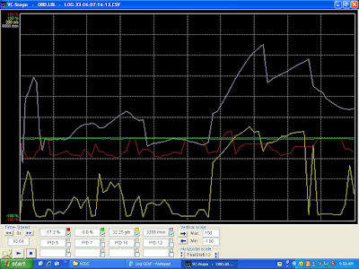
The air mass output (yellow trace) looks to mirror the engine speed (white Trace). The short term fuel trim (red trace) is negative during most of the data shown. the Long term fuel trim (green trace) is not showing much as the codes have just been cleared. This re-sets the long term fuel trim. I use this technique as the short term trim is for a short period of time is now reporting total fuelling adjustment.
From this we can establish that the engine is receiving too much fuel. This now makes sense, the P1141 code suggests that the load calculation does not agree with the data stored in the PCM look up tables.
How is load calculated? It depends on the system fitted to the vehicle, but typically it is the Throttle position, Manifold vacuum, engine speed, and air mass sensors that are used.
So the two codes are linked by the air mass, but it is a new unit. It couldn't be faulty could it?
By scoping the sensor we can eliminate the short to ground, the output looked good, no shorting out but the EPC light still illuminates.
 I checked with the the vehicle owner and a non OE air mass has been fitted. There are two different types for this variant of the Golf, does the local motor know this?
A new air mass sensor from Volkswagen was ordered, fitted and after a successful test drive the codes cleared and the vehicle returned to the owner.
So the warning here is modern engine management systems require precise inputs from the various sensors a variation as small as 0.2V will cause running problems, fault codes and legislative failures.
Monday, 9 August 2010
Braking News
Miss-diagnosis can be costly, the parts ordered non returnable and the time taken often un chargeable, but most importantly it can cost you good customers.

The 1st code lost communication with the transmission control module. The car is a manual but the 2nd hand control unit is from an automatic.

We were called to look at an Audi A6, the fault was an inoperative parking brake.
On these vehicles the hand brake is actuated electronically using a motor attached to a gear on the caliper. A control unit supplies the current, which is reversed to change the direction of rotation applying or releasing the brake.
The first garage had retrieved a fault code suggesting a power supply failure. Poor understanding of the operation of the system had led to a miss-diagnosis. They checked for voltage at the caliper upon finding no voltage they diagnosed the control unit. However the control unit runs self checks and if operating current is outside an operating tolerance the output is disabled to prevent cable burning or further damage.
The cost of a new control unit was considered prohibitive, so a second hand replacement was sought.....upon fitting the situation remained the same so the car was sent to another garage who specialises in VAG vehicles.
They fitted a new caliper, but this also failed to cure the problem. They then checked continuity between the caliper and the control unit and found an open circuit. The plug at the caliper had suffered water ingress and the cables had rotted away.
Confident they had found the fault the garage repaired the cables by soldering, however the control unit now showed a new code and one much more puzzling code.

The 1st code lost communication with the transmission control module. The car is a manual but the 2nd hand control unit is from an automatic.
The clamping force code relates to the method of detecting when the brakes are fully applied. The motor runs until the control current reaches around 15 amps this is the stop signal to the control unit. If 15 amps is not achieved within around 20-30 seconds the motor stops and the code is flagged.
This suggests that the motor is turning but the caliper is not clamping the disc. A rubber drive belt is used to transmit the torque from the motor to a gear of about 50:1 ratio. Could this be snapped. Could it be a wiring fault still? Is the caliper motor of the correct resistance. How can we quickly check?

In measuring value blocks 003 the control current is displayed.
The left hand caliper is drawing 5.852 amps.
Using ohms law we can calculate the resistance of the circuit 12/5.9 = 2.05 ohms.This is within the expected range, but why does it not clamp the disc.
To check if the rubber drive band is intact apply the handbrake with the footbrake applied.
If the current increases the motor is connected to the caliper. In this case it does.
This only leaves one possibility the wiring has been crossed during repair. Causing the left hand caliper to release the brakes instead of applying them.
So this proved to be the case, swapping the wires over restored correct operation.
Wednesday, 4 August 2010
Mercedes ML not so well
A local garage connected us about this a few days ago.
The owner complained of ticking noise from under the vehicle, and it had jumped from 4th to 1st gear. Now it will not drive but will start.
They checked for codes and P0300 was logged, random miss fire.
The garage suspected a fuel fault and checked fuel delivery, they discovered a very dirty fuel filter which was replaced. They then cleared the codes and tested the vehicle, not much better and now they had miss fire cyl 1, 2, & 3. So they checked the condition of the spark plugs, these were in poor condition so a new set was fitted.
However this had not improved the situation, they believed the dirty fuel (it was black coming out of the filter) had damaged the injectors. So they asked if we could take a look.
In cases such as these, it is tempting to carry on where the other garage left off. But this could be a mistake we always start with a few questions of the customer. (In this case the garage) Followed by a test drive to witness the fault and gather data. Then we test to prove what it is or in many cases what it isn't.
The test drive was brief the ML could hardly move itself off the forecourt.
Upon snapping open the throttle both O2 sensors went lean. If you coaxed the thing to rev they stayed lean. I normally perform a snap throttle acceleration of the engine to put a bit of strain on the ignition and fuelling systems.
These Mercedes prevent a full test by limiting the revs of the engine when the vehicle is stationary.
So having captured some live data, it was time to evaluate this data. The lean signal from both O2 sensors under snap acceleration and fast idle pointed towards a problem when the fuel demand increased. This was common to both banks so fuel pump testing became the obvious first test. We perform a number of different tests for fuel pumps. However we prefer not to break into any system so non intrusive amps clamp testing of the pump always features high on the list of preferred fuel pump tests.
We check the pump electrically and physically in one quick and easy test, and by analysing the waveform we can see bad pump sectors, freewheeling rotors and slow rotation.
In this case the return and fuel pressure regulator are part of the filter assembly, the fuel pipe is braided and prevents clamping to increase pressure to observe how the waveform reacts.
But satisfied the pumping element was OK, we tested the pressure at the rail and measured the flow rate checking for air in the fuel.
All was within specification, which ruled out a supply problem. Could the injectors be blocked by the contaminated fuel? They only way to find out is to remove and test on a flow bench. We can perform this test but as it requires dismantling of the fuel system, we decided to rule out all other suspects first.
What else could effect the fuelling on both banks?
Coolant temp sensor, air temp, air mass meter all sprung to mind.
The live data capture showed expected readings for coolant and air temp, the air mass is a much harder parameter to analyse a good rule of thumb is the idle reading in g/s the ML showed 8g/s at idle. I expect 10-14g/s from a 3.2L V6, so could we have an under estimating AMM. The resultant weak mixture the cause of the random miss fires, fuel trim is in the 30% range on both bank at fast idle.
A quick but not always accurate diagnosis can be made by disconnecting the AMM and trying the test drive again, if things improve then it certainly looks like the problem is in the remit of the AMM but doesn't mean the AMM itself has failed.
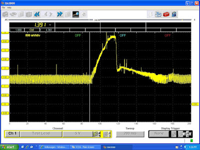
Testing with an oscilloscope is a much better bet, normally we look for at least 4V as the throttle is snapped open and 4.5V as it revs up to max rpm.
The ML has restricted rpm's when stationary but the trace below shows only 2.77V

A new AMM cured the problem here is the difference in scope trace the new AMM hit 3.2V stationary. The new AMM now read 12g/s at idle in live data.

Tuesday, 27 July 2010
Up's and down's of an electric window
This car had proved interesting, a flat battery combined with the wrong filament lamps in the brake lights meant it would not turn off with the key.
The reason the this Peugeot was booked in was a simple electric window fault.
Another garage had tried to find the fault but gave up. As the window would go down but not up they powered the motor from a 12v battery to send the window back up then disconnected the motor. This way the window could not be left stuck down.
As always it is the approach that is most important with any diagnostic job.
We always question the customer, this way we know what previous repairs have been carried out, thus the repair history.
In this case this proved very useful as we now know the motor works, even though it appears not to work at all.
Next we look at what does and doesn't work in this case the window can be controlled from the drivers door as well as the passenger door. So with the motor reconnected does it go down from both switches. Yes.
Looking at the wiring diagram which wire connects both switches and controls the current flow in the up direction? 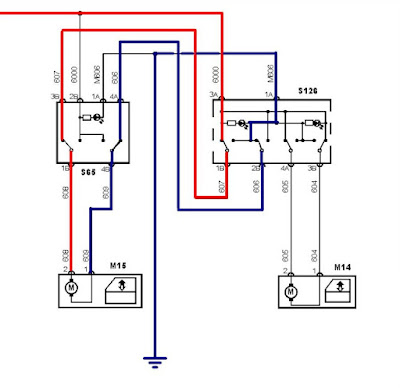
I am left with two options I have colored these in Red and Blue, Red the power supply for the motor and Blue earth in the up direction.To prove which is at fault I need to prove a loss of continuity between the passenger window switch and the drivers switch.
Most people would use a multi-meter set to ohms or the diode test position. We prefer to use current measurement for this test as it is dynamic. That is to say the circuit is in use. We needed to test between terminal 1b and 3b using the meter as the wires as the amp setting gives the meter very little resistance. Then 4a and 2b.
Knowing this before going to the car and testing reduces diagnostic time. Understanding the circuit means it can be tested quickly. It may take a few minutes before you pick up the meter but it can save hours.
In this case the wire between 4a and 2b was proved to be open circuit. This method proves the diagnosis as with the meter set to amps in place the window worked in both directions from both switches. The task of finding location of the broken wire is more difficult but knowing it was makes running another wire the quicker solution.
Subscribe to:
Posts (Atom)