The Peugeot 307 2.0 HDi came into the workshop with a history of failed repairs and an inventry of second hand parts fitted in an attempt to get it running correctly.
We have identified the ECU as the culprit, the internal earth path for the rail pressure sensor has failed.
With the ECU repaired, we could consider what has caused the rail pressure to increase without any command from the ECU.
The engine would start and idle but it would cut out when the rail pressure exceed set limits. (400+ bar)
We monitored the current drawn by the pressure regulator during the pressure increase and it did not alter.
This means the increase in pressure is down to a mechanical fault, not an electrical fault.
All high pressure fault diagnosis must start with the low pressure system.
In this case a higher low pressure could possibly result in higher, high pressure values.
A gauge was set up to monitor the low pressure, and an oscilloscope analysed the high pressure voltage from the rail pressure sensor. (Remember the original fault affected this sensor)
The engine was started and the rail pressure settled to a even 1.3V with a low pressure supply of 4.5 Bar.
Then the engine cut out. The Supply pressure remained constant however the rail pressure increased at the time the engine cut out.
The return lines were checked for damage and they all appeared to be fine, so what is causing the rise in rail pressure?
This is where system understanding is key to the diagnosis. The pressure is regulated by a valve, this valve allows fuel to bleed past to reduce the pressure. It has a spring inside that holds around 80-100 Bar in the rail when there is no current flowing to increase this pressure by means of an electro-magnet forcing the valve closed. A cranking check using live data showed the pressure was in excess of 120Bar in live data with the valve disconnected.
The valve must be sticking or blocked. The valve can be removed for replacement or inspection.
In this case a large amount of metal swarf was found inside the fine filter that is fitted, this must be preventing the fuel escaping. We cleaned the filter and replaced the valve. The swarf must be coming from the fuel system, and without a comprehensive repair history, we could not be certain the fault had been repaired or was the component still breaking down.
Due to the high costs involved it was decided that the best way forward was to return the vehicle to the customer. The vehicle has been driven for 3-5 thousand miles without issue.
Showing posts with label Electrical fault finding Automotive. Show all posts
Showing posts with label Electrical fault finding Automotive. Show all posts
Friday, 17 August 2012
Friday, 30 December 2011
P0420 the most common fault code?
P0420 is possibly the most common DTC retrieved from modern vehicles.
This is because it is one of the codes that is concerned with the exhaust system, any fault upstream of the exhaust can result in a P0420 code.
This why it can be cleared and not return or cleared only to return but not always immediately.
The catalyst can be damaged by many things, but misfire is the most common cause of catalyst damage. P0420 indicates the catalyst is operating below some threshold set within the ECU software. It can be a temporary fault or an indication of catalyst failure.
It is monitored by the O2 sensors, one before the catalyst and one after the catalyst. The two signals are compared and if they are similar the ECU flags the code.

Above is a scan tool image of a catalyst operating efficiently.
There are number of ways to test the catalyst efficiency
- use an infra red thermometer to check for an increase in temperature across the catalyst
- Scan tool data to monitor the switch ratio before and after the catalyst
- oscilloscope to check O2 signal output
- Gas analyser to check readings
- EOBD mode 6
Always test the catalyst under the most favourable conditions, as this is how the ECU tests the catalyst. Hot engine, fast idle/cruise and no other faults present.
The ECU will only monitor the the catalyst efficiency if there are no codes stored. Therefore it is essential to check the catalyst before returning the vehicle to the customer, if a fault has been repaired that may have damaged the catalyst, such as coil pack failure.
Remember it is the O2 sensor that is used to monitor the catalyst so these must be operating correctly.
Tuesday, 27 July 2010
Up's and down's of an electric window
This car had proved interesting, a flat battery combined with the wrong filament lamps in the brake lights meant it would not turn off with the key.
The reason the this Peugeot was booked in was a simple electric window fault.
Another garage had tried to find the fault but gave up. As the window would go down but not up they powered the motor from a 12v battery to send the window back up then disconnected the motor. This way the window could not be left stuck down.
As always it is the approach that is most important with any diagnostic job.
We always question the customer, this way we know what previous repairs have been carried out, thus the repair history.
In this case this proved very useful as we now know the motor works, even though it appears not to work at all.
Next we look at what does and doesn't work in this case the window can be controlled from the drivers door as well as the passenger door. So with the motor reconnected does it go down from both switches. Yes.
Looking at the wiring diagram which wire connects both switches and controls the current flow in the up direction? 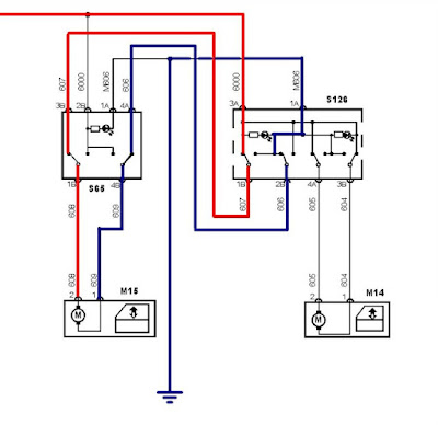
I am left with two options I have colored these in Red and Blue, Red the power supply for the motor and Blue earth in the up direction.To prove which is at fault I need to prove a loss of continuity between the passenger window switch and the drivers switch.
Most people would use a multi-meter set to ohms or the diode test position. We prefer to use current measurement for this test as it is dynamic. That is to say the circuit is in use. We needed to test between terminal 1b and 3b using the meter as the wires as the amp setting gives the meter very little resistance. Then 4a and 2b.
Knowing this before going to the car and testing reduces diagnostic time. Understanding the circuit means it can be tested quickly. It may take a few minutes before you pick up the meter but it can save hours.
In this case the wire between 4a and 2b was proved to be open circuit. This method proves the diagnosis as with the meter set to amps in place the window worked in both directions from both switches. The task of finding location of the broken wire is more difficult but knowing it was makes running another wire the quicker solution.
Subscribe to:
Comments (Atom)