Wednesday, 4 August 2010

Mercedes ML not so well

A local garage connected us about this a few days ago.
The owner complained of ticking noise from under the vehicle, and it had jumped from 4th to 1st gear. Now it will not drive but will start.
They checked for codes and P0300 was logged, random miss fire.

The garage suspected a fuel fault and checked fuel delivery, they discovered a very dirty fuel filter which was replaced. They then cleared the codes and tested the vehicle, not much better and now they had miss fire cyl 1, 2, & 3. So they checked the condition of the spark plugs, these were in poor condition so a new set was fitted.

However this had not improved the situation, they believed the dirty fuel (it was black coming out of the filter) had damaged the injectors. So they asked if we could take a look.

In cases such as these, it is tempting to carry on where the other garage left off. But this could be a mistake we always start with a few questions of the customer. (In this case the garage) Followed by a test drive to witness the fault and gather data. Then we test to prove what it is or in many cases what it isn't.

The test drive was brief the ML could hardly move itself off the forecourt.

Upon snapping open the throttle both O2 sensors went lean. If you coaxed the thing to rev they stayed lean. I normally perform a snap throttle acceleration of the engine to put a bit of strain on the ignition and fuelling systems.

These Mercedes prevent a full test by limiting the revs of the engine when the vehicle is stationary.

So having captured some live data, it was time to evaluate this data. The lean signal from both O2 sensors under snap acceleration and fast idle pointed towards a problem when the fuel demand increased. This was common to both banks so fuel pump testing became the obvious first test. We perform a number of different tests for fuel pumps. However we prefer not to break into any system so non intrusive amps clamp testing of the pump always features high on the list of preferred fuel pump tests.

We check the pump electrically and physically in one quick and easy test, and by analysing the waveform we can see bad pump sectors, freewheeling rotors and slow rotation.

In this case the return and fuel pressure regulator are part of the filter assembly, the fuel pipe is braided and prevents clamping to increase pressure to observe how the waveform reacts.

But satisfied the pumping element was OK, we tested the pressure at the rail and measured the flow rate checking for air in the fuel.

All was within specification, which ruled out a supply problem. Could the injectors be blocked by the contaminated fuel? They only way to find out is to remove and test on a flow bench. We can perform this test but as it requires dismantling of the fuel system, we decided to rule out all other suspects first.

What else could effect the fuelling on both banks?
Coolant temp sensor, air temp, air mass meter all sprung to mind.

The live data capture showed expected readings for coolant and air temp, the air mass is a much harder parameter to analyse a good rule of thumb is the idle reading in g/s the ML showed 8g/s at idle. I expect 10-14g/s from a 3.2L V6, so could we have an under estimating AMM. The resultant weak mixture the cause of the random miss fires, fuel trim is in the 30% range on both bank at fast idle.

A quick but not always accurate diagnosis can be made by disconnecting the AMM and trying the test drive again, if things improve then it certainly looks like the problem is in the remit of the AMM but doesn't mean the AMM itself has failed.
Testing with an oscilloscope is a much better bet, normally we look for at least 4V as the throttle is snapped open and 4.5V as it revs up to max rpm.
The ML has restricted rpm's when stationary but the trace below shows only 2.77V


A new AMM cured the problem here is the difference in scope trace the new AMM hit 3.2V stationary. The new AMM now read 12g/s at idle in live data.




Tuesday, 27 July 2010

Up's and down's of an electric window

This car had proved interesting, a flat battery combined with the wrong filament lamps in the brake lights meant it would not turn off with the key.


The reason the this Peugeot was booked in was a simple electric window fault.


Another garage had tried to find the fault but gave up. As the window would go down but not up they powered the motor from a 12v battery to send the window back up then disconnected the motor. This way the window could not be left stuck down.


As always it is the approach that is most important with any diagnostic job.


We always question the customer, this way we know what previous repairs have been carried out, thus the repair history.


In this case this proved very useful as we now know the motor works, even though it appears not to work at all.


Next we look at what does and doesn't work in this case the window can be controlled from the drivers door as well as the passenger door. So with the motor reconnected does it go down from both switches. Yes.


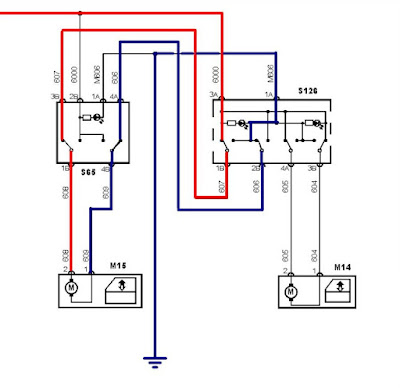
Looking at the wiring diagram which wire connects both switches and controls the current flow in the up direction?

I am left with two options I have colored these in Red and Blue, Red the power supply for the motor and Blue earth in the up direction.To prove which is at fault I need to prove a loss of continuity between the passenger window switch and the drivers switch.

Most people would use a multi-meter set to ohms or the diode test position. We prefer to use current measurement for this test as it is dynamic. That is to say the circuit is in use. We needed to test between terminal 1b and 3b using the meter as the wires as the amp setting gives the meter very little resistance. Then 4a and 2b.

Knowing this before going to the car and testing reduces diagnostic time. Understanding the circuit means it can be tested quickly. It may take a few minutes before you pick up the meter but it can save hours.

In this case the wire between 4a and 2b was proved to be open circuit. This method proves the diagnosis as with the meter set to amps in place the window worked in both directions from both switches. The task of finding location of the broken wire is more difficult but knowing it was makes running another wire the quicker solution.

Thursday, 15 July 2010

Pugilistic Pug

This 306 came with a list of electrical problems, no big deal or so I thought.
The high priority job was enable the engine to stop on the key.
This is a safety critical repair, the first task was to get the engine started, the battery was completely discharged. A sure sign of the trouble ahead.
Once the engine started with a booster pack, you could remove the key and the thing kept running until you switched the lights on then off!
I fitted a replacement battery after cleaning all traces of electrolyte from the battery tray and surrounding areas. This restored the key to normal operation, but the side lights refused to switch off, plus the brake lights were on permanently.
The culprit, the brake switch had become dislodged. With the switch re-fitted and correctly adjusted we now had working brake lights, however the side lights came on every time the brakes were applied. I was beginning to think this was some sort of joke, but this is normally a simple case of incorrect filament lamps being fitted. Sure enough one of the brake light lamps was a single filament instead of a double filament, this back feeds the side light circuit putting the side lights on whenever the brake pedal is pressed.
The list of jobs was slowly reducing, but now I had to sort the passenger electric window. More on this next time.

Tuesday, 1 June 2010

Blinded by the light

This got me thinking. The Mk 5 golf with an error message for lamp failure.
Simple enough at first glance. (You can read more about the fault in an earlier post).
It turned out to be the side light/brake light that was inoperative.

I checked the lamp visually it appeared fine, so I measured it's resistance it showed 0.6 ohms.

This is the bit that got me thinking..............is that right? I compared it with the working side light and it too had a resistance of 0.6 ohms. So it is correct. Or is it?

These cars and many newer vehicles have done away with many of the fuses and use the ECU's to monitor faults, if any faults are detected it simply switches off the outputs. Then a warning is displayed in the dash panel. The joys of vehicle networks.

I set about some calculations to find out if the measured resistance was correct.

I knew the bulb rating 21W 12V therefore I could work out the current flow.
P= I x V
I =P/V = 21/12 = 1.75 Amps

Ohms law states I = V/R
R = V/I = 12/1.75 = 6.9 Ohms

So why was the resistance of the lamp filament so wrong?
Lamps convert heat into light, heating a conductor will increase its resistance. A lamp will show around 1/10th of its operating resistance in a "cold" measurement.


This can be clearly seen in the scope trace above, this was taken after I repaired a high circuit resistance in the wiring to the lamp. (the cause of the lamp failure warning you can read about in an earlier post).
Notice the "cold" resistance is much lower than the "hot" resistance seen as a high current 11 Amps falling to the operating current of 2 Amps. Notice how the Body ECU warms the filament with a short burst of current before switching the lamp on this stops current spikes and prolongs filament life.

Noble part 2

This car has proved difficult to diagnose, an intermittent miss fire, normally under load had proved elusive. Weather conditions, lack of rolling road time, along with fixing other basic problems had turned this into a bit of a saga.

Having checked the inputs/outputs of the ECU, everything appeared fine. However the car would occasionally cut out. Once this happened it would re-start and perform without fault for ever decreasing amounts of time. The ECU was inspected and tested and was found to be ok.

I turned my attention to the coils, these showed good current ramping (below), but it was during these tests the car cut out. The output just vanished.

This means the ECU has stopped grounding the coils, but why? Could it still be an ECU fault?

I decided to investigate further, a check with the local Ford parts department proved fruitful.

The coils have been super seeded.


We tried a new coil to see if there is any noticeable difference. The current trace (above) shows the subtle but measurable difference. A further 5 coils were ordered and the car returned to the rollers. We now had closer to the rated output and no miss fires!

Monday, 24 May 2010

Have you seen the light?

This could be one of the most difficult faults to diagnose on modern vehicles.
A Golf MK V has a side light/brake light failure, however the local garage and the main agent have come to an expensive conclusion. It must be the body system interface. This computer controls many of the body and lighting functions on the vehicle. Replacement is costly not just the parts but the time plugged into the dealer diagnostic interface "coding" the unit.

This vehicle has few relays and even fewer fuses. The circuit at fault has no apparent circuit protection. If a fault is detected by the body interface it simply turns off the supply.
This in turn puts a fault light and message on the multi function display on the dash.

This vehicle had no such message or warning light. No fault codes were found in the body system interface. The lamp had been checked and passed both visual and resistance checks.
Yet when the side lights were switched on, or the brake pedal depressed the lamp failed to light.
The previous repair shops had checked for voltage at the lamp, and the output of the BSI.
No voltage means no output from the BSI, with no codes the garages had assumed this meant an ecu fault.

Is this diagnosis correct?
The main agent was unsure and requested we checked the system. The BSI checks for faults two ways termed hot and cold monitoring.
Cold monitors run every time the ign is switched on, hot monitors run while the circuit is in use.
A quick check with the scope showed the cold monitor was indeed running. So why was there no output, and if the was a circuit fault why no code? Or warning light/message?

You will often hear me banging my drum about Voltage Drop testing, however this can only be carried out with the circuit in use. ( Dynamic Testing) in this case this is not possible, so we tested using resistance checks, first continuity to ground (short to earth) then short to live with no fault error message we expected these simple checks to be fruitless. So it proved.
However the resistance between the BSi and the lamp showed 57 Ohms. Bingo this test was then repeated along the loom until the section at fault was identified. A loom connection proved to be the culprit showing signs of corrosion, and once cleaned and protected from further water Ingres normal operation was restored. It appears the fault is outside the fault code parameters but within the fault limit. This results in no output and no warning light/message on the multi function display. This has to be the worse case for the technician.

Tuesday, 27 April 2010

ABS Diagnosis

Customer complaining of noise and brake judder, booked into a local garage for pads and discs.
These were fitted and the fault remained!
The garage checked for codes but as the ABS light was not illuminated they were not surprised to find a clean bill of health. No codes found.
I was asked to check the braking system and report my findings.
A quick test drive proved the ABS to be operating, but not when you expected.
In cases like this I like to remove the ABS fuse to disable the system, then perform a road test. This careful road test, remembering the ABS will not operate can prove if it is an ABS control or operating fault, or a mechanical fault in the braking system.
In this case the car now performed faultlessly. Proving an ABS fault.
But without fault codes how can it be diagnosed quickly?
Start with a visual check, and sure enough the reason was clear to see a cracked reluctor ring.
Not easy to spot, but easy to see with the scope.