We were called to look at a race car that had a Ford Cosworth V6 engine fitted in place of the original Essex V6. This conversion should in theory free up 50-60 bhp, however the engine would not fire.
This engine ran the old Ford EDIS ignition set up, with a separate ecu providing the fuel.
The fuel ecu modifies the ignition timing after receiving a digital signal from the EDIS module. It uses this signal for its speed/position reference.
As there was no fuel or spark it seemed logical to start with this signal. But only after checking for the correct lives and earths at both ecus. We corrected a number of wiring errors, and thought we might have sorted the problem. But it still refused to fire up.
We checked for the PIP signal.
PIP is the Ford term for the speed/position reference signal (profile ignition pickup).
There was no output from the EDIS. Next step is to check the input.
 This is a simple inductive crank sensor from the front pulley. There was a signal, however it was different from the expected signal. We suspected the crank sensor was the culprit. A quick resistance check showed a normal 0.8K ohms, this is why an oscilloscope is essential, if we had just used a meter, we would have an AC frequency and the correct resistance readings. This would then suggest a fault with the EDIS module.
Input - logic- Output model would lead to miss diagnosis of the module as there was no output despite the correct power, ground and inputs.
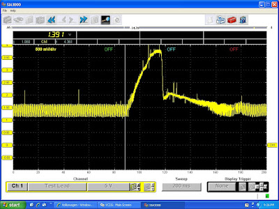
Unable to find a replacement sensor on the self we rigged up a CKS from a Renault using a cable tie and two jumper wires. result is shown below.

The yellow trace is the CKS and the green trace the PIP.
The ECU was now injecting and the coil pack sparking. The difference between the two CKS traces is the waveform around the missing tooth. The jump in the waveform is due to the spark plugs being out of the engine causing RFi made worse by the exposed makeshift CKS wiring.
Another successful diagnosis due to the oscilloscope being able to display the full picture.


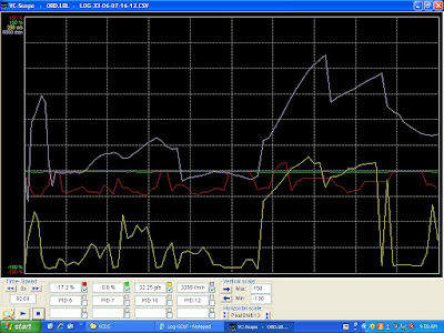
 I checked with the the vehicle owner and a non OE air mass has been fitted. There are two different types for this variant of the Golf, does the local motor know this?


