Monday, 30 August 2010

Fore!

This Golf scenario starts with the traditional Golfing warning of a stray shot.
Fore!
I am often asked to check or to diagnose faults after another workshop has diagnosed the vehicle. This is sometimes at the request of the vehicle owner or the workshop.
A second opinion is sometimes sort if the repairs are costly bizarre or if the workshop can't make head nor tail of the data presented.

This Golf had a running fault which was diagnosed as the Air Mass Meter. A new unit was fitted the codes cleared and the vehicle given back to the owner.

The malfunction indicator lamp or MIL was no longer illuminated, however the car felt flat and was using an alarming amount of petrol.
The EPC warning light would illuminate above 4000rpm and extinguish once the rev's dropped.
The garage agreed to look at the car for no extra charge but could not determine what was wrong, the fault code or DTC was for a short to positive at the air mass meter. They could find no such fault.

I was asked to look at the vehicle, I took it for a test drive observing data driving style and the performance or lack of it.

Using the VCDS software on the laptop I was able to retrieve all the fault codes stored.


P1145 Mass Air Flow Sensor Short to Positive


P1141 Load calculation cross check : implausible value

The next step is to establish what is the data telling us, using the graphing function of the VCDS software.


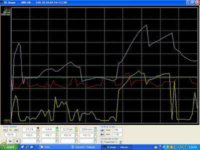
The air mass output (yellow trace) looks to mirror the engine speed (white Trace). The short term fuel trim (red trace) is negative during most of the data shown. the Long term fuel trim (green trace) is not showing much as the codes have just been cleared. This re-sets the long term fuel trim. I use this technique as the short term trim is for a short period of time is now reporting total fuelling adjustment.


From this we can establish that the engine is receiving too much fuel. This now makes sense, the P1141 code suggests that the load calculation does not agree with the data stored in the PCM look up tables.


How is load calculated? It depends on the system fitted to the vehicle, but typically it is the Throttle position, Manifold vacuum, engine speed, and air mass sensors that are used.


So the two codes are linked by the air mass, but it is a new unit. It couldn't be faulty could it?

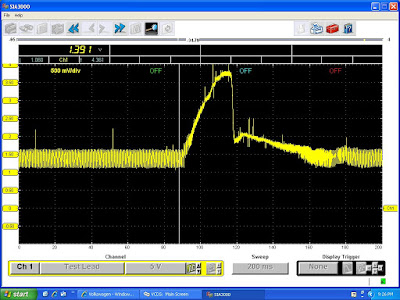
By scoping the sensor we can eliminate the short to ground, the output looked good, no shorting out but the EPC light still illuminates.

I checked with the the vehicle owner and a non OE air mass has been fitted. There are two different types for this variant of the Golf, does the local motor know this?

A new air mass sensor from Volkswagen was ordered, fitted and after a successful test drive the codes cleared and the vehicle returned to the owner.

So the warning here is modern engine management systems require precise inputs from the various sensors a variation as small as 0.2V will cause running problems, fault codes and legislative failures.

Monday, 9 August 2010

Braking News

Miss-diagnosis can be costly, the parts ordered non returnable and the time taken often un chargeable, but most importantly it can cost you good customers.

We were called to look at an Audi A6, the fault was an inoperative parking brake.
On these vehicles the hand brake is actuated electronically using a motor attached to a gear on the caliper. A control unit supplies the current, which is reversed to change the direction of rotation applying or releasing the brake.
The first garage had retrieved a fault code suggesting a power supply failure. Poor understanding of the operation of the system had led to a miss-diagnosis. They checked for voltage at the caliper upon finding no voltage they diagnosed the control unit. However the control unit runs self checks and if operating current is outside an operating tolerance the output is disabled to prevent cable burning or further damage.
The cost of a new control unit was considered prohibitive, so a second hand replacement was sought.....upon fitting the situation remained the same so the car was sent to another garage who specialises in VAG vehicles.
They fitted a new caliper, but this also failed to cure the problem. They then checked continuity between the caliper and the control unit and found an open circuit. The plug at the caliper had suffered water ingress and the cables had rotted away.
Confident they had found the fault the garage repaired the cables by soldering, however the control unit now showed a new code and one much more puzzling code.


The 1st code lost communication with the transmission control module. The car is a manual but the 2nd hand control unit is from an automatic.

The clamping force code relates to the method of detecting when the brakes are fully applied. The motor runs until the control current reaches around 15 amps this is the stop signal to the control unit. If 15 amps is not achieved within around 20-30 seconds the motor stops and the code is flagged.

This suggests that the motor is turning but the caliper is not clamping the disc. A rubber drive belt is used to transmit the torque from the motor to a gear of about 50:1 ratio. Could this be snapped. Could it be a wiring fault still? Is the caliper motor of the correct resistance. How can we quickly check?

In measuring value blocks 003 the control current is displayed.

The left hand caliper is drawing 5.852 amps.

Using ohms law we can calculate the resistance of the circuit 12/5.9 = 2.05 ohms.This is within the expected range, but why does it not clamp the disc.

To check if the rubber drive band is intact apply the handbrake with the footbrake applied.
If the current increases the motor is connected to the caliper. In this case it does.
This only leaves one possibility the wiring has been crossed during repair. Causing the left hand caliper to release the brakes instead of applying them.
So this proved to be the case, swapping the wires over restored correct operation.


Wednesday, 4 August 2010

Mercedes ML not so well

A local garage connected us about this a few days ago.
The owner complained of ticking noise from under the vehicle, and it had jumped from 4th to 1st gear. Now it will not drive but will start.
They checked for codes and P0300 was logged, random miss fire.

The garage suspected a fuel fault and checked fuel delivery, they discovered a very dirty fuel filter which was replaced. They then cleared the codes and tested the vehicle, not much better and now they had miss fire cyl 1, 2, & 3. So they checked the condition of the spark plugs, these were in poor condition so a new set was fitted.

However this had not improved the situation, they believed the dirty fuel (it was black coming out of the filter) had damaged the injectors. So they asked if we could take a look.

In cases such as these, it is tempting to carry on where the other garage left off. But this could be a mistake we always start with a few questions of the customer. (In this case the garage) Followed by a test drive to witness the fault and gather data. Then we test to prove what it is or in many cases what it isn't.

The test drive was brief the ML could hardly move itself off the forecourt.

Upon snapping open the throttle both O2 sensors went lean. If you coaxed the thing to rev they stayed lean. I normally perform a snap throttle acceleration of the engine to put a bit of strain on the ignition and fuelling systems.

These Mercedes prevent a full test by limiting the revs of the engine when the vehicle is stationary.

So having captured some live data, it was time to evaluate this data. The lean signal from both O2 sensors under snap acceleration and fast idle pointed towards a problem when the fuel demand increased. This was common to both banks so fuel pump testing became the obvious first test. We perform a number of different tests for fuel pumps. However we prefer not to break into any system so non intrusive amps clamp testing of the pump always features high on the list of preferred fuel pump tests.

We check the pump electrically and physically in one quick and easy test, and by analysing the waveform we can see bad pump sectors, freewheeling rotors and slow rotation.

In this case the return and fuel pressure regulator are part of the filter assembly, the fuel pipe is braided and prevents clamping to increase pressure to observe how the waveform reacts.

But satisfied the pumping element was OK, we tested the pressure at the rail and measured the flow rate checking for air in the fuel.

All was within specification, which ruled out a supply problem. Could the injectors be blocked by the contaminated fuel? They only way to find out is to remove and test on a flow bench. We can perform this test but as it requires dismantling of the fuel system, we decided to rule out all other suspects first.

What else could effect the fuelling on both banks?
Coolant temp sensor, air temp, air mass meter all sprung to mind.

The live data capture showed expected readings for coolant and air temp, the air mass is a much harder parameter to analyse a good rule of thumb is the idle reading in g/s the ML showed 8g/s at idle. I expect 10-14g/s from a 3.2L V6, so could we have an under estimating AMM. The resultant weak mixture the cause of the random miss fires, fuel trim is in the 30% range on both bank at fast idle.

A quick but not always accurate diagnosis can be made by disconnecting the AMM and trying the test drive again, if things improve then it certainly looks like the problem is in the remit of the AMM but doesn't mean the AMM itself has failed.
Testing with an oscilloscope is a much better bet, normally we look for at least 4V as the throttle is snapped open and 4.5V as it revs up to max rpm.
The ML has restricted rpm's when stationary but the trace below shows only 2.77V


A new AMM cured the problem here is the difference in scope trace the new AMM hit 3.2V stationary. The new AMM now read 12g/s at idle in live data.