Friday, 28 August 2009

Testing Earth Circuits


The way in which earth circuits are tested is a critical step in your diagnostic routine.
Becoming familiar with effective ways to test Earth's will save trouble and miss diagnosis.
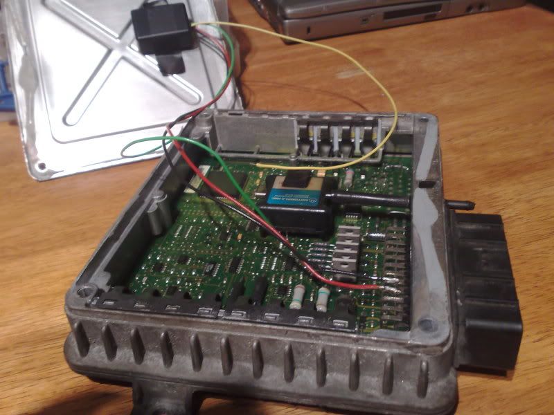
Recently I was asked to look into a V.A.G. vehicle with a fault code that would not clear, despite the changing of many of the components, including relays, sensors and the ECU.
A test of the earth circuit proved a high resistance at the Earth point on the bulkhead.
A simple clean up of the connector and the application of some battery post grease restored normal operation.
But how do you test earths effectively?
The answer is Volt drop, measure the earth circuit just like you would test the voltage in a battery.
However the circuit must be use and the results should be no more than 0.2V or 0.5V cranking.

Sunday, 23 August 2009

Turbo Trouble


Had to fix this one, I bought a vehicle as it had a running problem that couldn't be fixed.

Or so it appeared, it was owned by a mechanic and despite spending a considerable sum of money on the car over the last few months he had given up.

The car in question was a Rover 620 ti, this uses the MEMS engine management system.

It is important to note what system is fitted before diagnosis can take place, different systems handle errors in different ways.

The problem was a starting fault that got worse when the engine was hot.

First things first with any diagnosis, the basics, this includes 10mins of look and feel, making sure the car has fuel in it.

To that end 30 litres of fuel were purchased.

A quick code read showed multiple codes, no doubt due to removing sensors connections and testing by the previous owner. As a starting fault it is possible to clear codes, to eliminate any historic codes and only current codes relevant to the fault will remain.

As the car will not start at all when hot, this will prove beneficial, reducing the number of tests required to prove the diagnosis.

The fault code remaining was Map sensor.

This didn't concern too much, but a look at live data showed a reading of 800-830KPa at idle once it had cooled down and eventually started. The expected value would be 300-350.

Such poor engine vacuum would give the sort of fault I was faced with, but the car drove too well to have a engine problem. plus this MEMS system will use the TPS (throttle position sensor) value as a substitute for MAP values giving engine load information to the ECU.

I tested for coil and injector outputs from the ECU during cranking. All Ok.

But his doesn't prove fuel delivery, so a quick fuel pump test as used on the formula Renault's proved the pumps ability to deliver fuel, and a pressure test showed normal results.

As this left no other explanation for the non/poor start it must be the erroneous MAP reading that is the cause, as the MAP sensor is inside the ECU it normally requires a replacement ECU.

However in the paperwork with the car I noticed a receipt for a Collins power chip.

This 'chip' is a frequency limiter that prevents fuel cut off above a given boost pressure allowing more than standard boost pressure.

It was found that to fit this 'chip' requires soldering a by pass wire in the MAP sensor circuit.

This soldered joint had failed, a quick visit with the soldering iron restored normal starting and improved performance from the increased levels of boost.


Word of caution do not increase boost levels above 12psi on this engine without internal modifications as piston failure will result.

Tuesday, 11 August 2009

Smokin' Fuel Pump relay


Formula Renault single seater, running mappable
ECU was getting hot under the collar.
To carry on racing the relay had been by-passed.
However this isn't safe practice and the cause had to be found.
The rating of the relay was checked to ensure it was up to the job. Then the current draw of another car was measured. (left).
A peak of 12 amps and a running current of aroun 10 amps.

With this in mind I was expecting to find a fault either in the wiring or the pump resulting in a much higher current draw. This was measured at the pump wiring with the by pass fitted. This would exclude the ECU and associated wiring. the result is shown. (right).
A peak of 14 amps and a running current of 12 amps, however it is running much slower than the previously tested pump.
When tested at the relay (with the by-pass wiring removed) no current draw was observed.
The car would not start, and the fuel pump refused to prime.
Closer inspection found a broken terminal going into the relay block. Not on the relay that was getting hot but on another that shared '+' feeds.
Once repaired and re tested none of the relays were smoking and the car barked into life.
I quick check of the 'fuel pump relay' showed little more than 0.2 A draw, it wasn't the fuel pump relay, but the ECU supply. The broken wiring resulted in back feeding and this in turn over heated the relay circuit. Re routing and not securing the relay block to the chassis should prevent it happening again.


Monday, 10 August 2009

Door won't open!!


Just had to let you guys know about this one.

A workshop had spent hours trying to open the door on a Peugeot 1007.

Convinced they had a door lock fault they had almost destroyed the trim on the door trying to remove it, while the door remained firmly locked.

A global scan, that is a scan of all the electronic control units fitted to the vehicle revealed a fault code relating to the fuel filler cap. A new filler cap sensor and loom was fitted and hey presto the door opened.

But why, these vehicles are fitted with a sliding door that is prevented from opening when the filler cap is opened. This is a safety issue as the door would hit the fuel nozzle if it could be opened during re fuelling. With the sensor faulty the safe mode is locked.